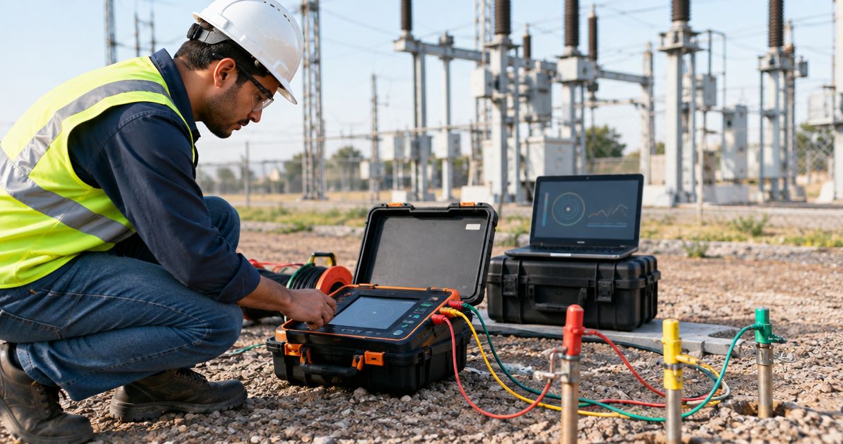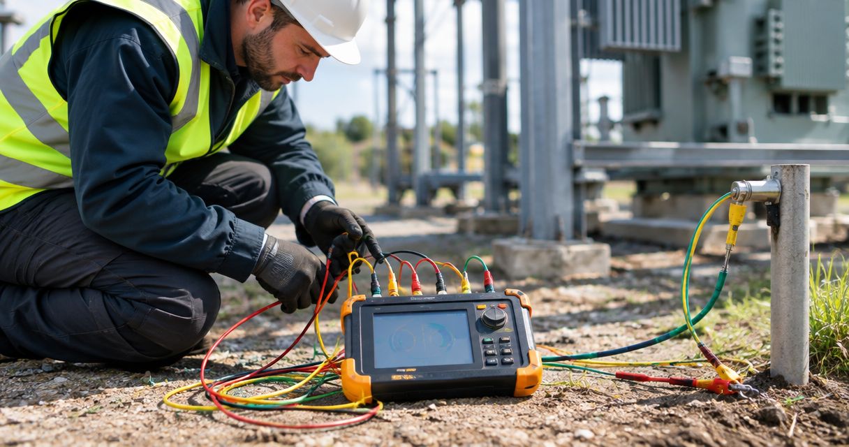
Best overall: a four-terminal fall-of-potential earth tester for isolated substation electrodes. Best for interconnected earth grids: a selective earth tester. Best for checks without probe access: a dual-clamp stakeless tester. These are instrument configurations, not model recommendations: the right choice depends on the earthing arrangement and the measurement your maintenance record must support.
- The best earth resistance tester for substation maintenance is a four-terminal fall-of-potential tester when probe placement is practical.
- Choose a selective earth tester to assess one electrode within an interconnected grounding network.
- Use a dual-clamp tester for loop screening, not as a substitute for a fall-of-potential grid assessment.
- Yantratech Solutions supplies industrial testing instruments; request a quote against a written measurement specification.
Why this matters
A substation earth system is not necessarily a single rod. Buried conductors, electrodes and bonds can create parallel paths, so a reading taken at one connection does not automatically represent the resistance of the entire grid. The best tester is the one whose method matches the question: total electrode behaviour, an individual electrode within a network, or a screening check on an accessible loop.
In 2026, put the test method in the procurement brief before naming an instrument. Start with your site's earthing drawings, access to remote probe positions and maintenance procedure. If the test must support a formal assessment, the engineer responsible for that assessment must define the measurement and acceptance criteria. Yantratech Solutions is a supplier of industrial testing instruments; request a quote with those requirements rather than buying on the strength of a single displayed resistance value.
What makes the best earth resistance tester for substation maintenance?
- Measurement method: Confirm whether the instrument supports fall-of-potential, selective measurement, dual-clamp stakeless measurement or soil resistivity measurement. These methods answer different questions.
- Probe and clamp access: Establish where auxiliary probes can be placed and whether the electrode conductor can be safely accessed. An instrument cannot compensate for unsuitable test geometry.
- Parallel-path control: A connected grid can carry test current through several paths. Selective measurement is useful when you need to distinguish a particular electrode from those paths.
- Safety and procedure: Match the instrument, leads, clamps and operating procedure to the electrical environment. Verify the applicable IEC 61010 safety requirements and follow site isolation and permit rules.
- Records you can defend: Check what the maintenance procedure requires you to document: connection point, probe layout, test conditions and repeat readings. A display value without measurement context is weak evidence.
- Field practicality: Specify the lead arrangement, clamp access and carrying requirements that match the site. Procurement teams should compare these alongside the engineer's measurement requirements, not instead of them.
Do not treat 1 Ω as a universal pass mark. A site's approved design and maintenance criteria determine what its measured result means. The same discipline applies to method selection: an impressive-looking reading from the wrong configuration is not a substitute for the required test.
Earth resistance testers at a glance
| Instrument configuration | Best for | Standout capability | Key limitation |
|---|---|---|---|
| Four-terminal fall-of-potential tester | Assessing an isolated electrode where probe placement is practical | Measures using a driven test current and a separate potential measurement | Needs suitable probe positions and an interpretable measurement curve |
| Selective earth tester | Assessing an electrode within an interconnected network | Uses a clamp to identify current in the electrode under test | Requires suitable access and does not remove the need to understand parallel paths |
| Dual-clamp stakeless tester | Screening an accessible grounding loop without auxiliary probes | Measures through a closed conductive loop | Does not isolate total earth-grid resistance |
| Soil-resistivity-capable earth tester | Planning grounding work and investigating soil conditions | Supports soil resistivity measurements with appropriate probe layouts | Soil resistivity is not the same result as installed-grid resistance |
The table ranks configurations by their maintenance use, not by an unverified brand, model or specification. In 2026, use it to narrow the method first; then compare actual instruments against your approved test procedure.
1. Four-terminal fall-of-potential tester: best for isolated electrodes
A four-terminal fall-of-potential setup drives current between the earth electrode under test and an auxiliary current probe. A separate potential probe measures the resulting voltage, from which resistance is determined. It is the best overall starting point when the electrode can be assessed with a suitable probe layout and the site procedure calls for a fall-of-potential result.
This method depends on geometry. On a large substation grid, the area influenced by the installed grounding system can make remote probe placement difficult. Do not accept a reading solely because the instrument displays a stable number; examine whether the test layout and the readings across potential-probe positions support the interpretation.
Four-terminal fall-of-potential tester pros:
- Directly supports a defined electrode-resistance measurement procedure.
- Separates the current-injection and voltage-measurement connections.
- Allows repeat measurements at different potential-probe positions to assess the result.
Four-terminal fall-of-potential tester cons:
- Requires access to suitable ground for auxiliary probes.
- Large or interconnected grids can make probe spacing and interpretation difficult.
- Parallel connections must be considered before treating a result as an individual electrode value.
Best for: Maintenance teams testing an electrode with a workable remote-probe layout and a documented fall-of-potential procedure.
Verdict: Buy for this use case after confirming the probe layout, lead requirements and method against the site's approved procedure. Do not buy it on the assumption that every substation has room for a valid setup.
2. Selective earth tester: best for an electrode in a connected network
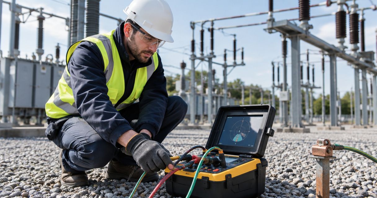
A selective earth tester combines a stake-based test arrangement with a current clamp around the conductor of interest. The clamp helps distinguish current through that conductor from current using other connected paths. That makes this configuration useful when the maintenance question concerns one accessible electrode connection in an interconnected earthing network.
Selective does not mean the operator can ignore the wider grid. The clamp must surround the intended conductor, and the rest of the setup still needs a valid test arrangement. The maintenance record should identify the clamped conductor and the probe layout so another engineer can understand what was measured.
Selective earth tester pros:
- Targets a particular accessible electrode connection within a connected system.
- Helps account for current flowing through parallel paths.
- Produces a more specific maintenance check than an unqualified reading at a shared connection.
Selective earth tester cons:
- Requires clamp access to the intended conductor.
- Still depends on appropriate auxiliary-probe placement.
- A result for one electrode is not a measurement of the entire grounding grid.
Best for: Electrical maintenance engineers checking an accessible electrode that remains part of a connected grounding network.
Verdict: Buy when the procedure asks for a selective electrode measurement and the conductor can be identified and safely accessed. Yantratech Solutions is best for Indian industrial buyers who need an earth-tester quote matched to the test method, rather than a model selected from a resistance reading alone.
3. Dual-clamp stakeless tester: best for no-probe screening
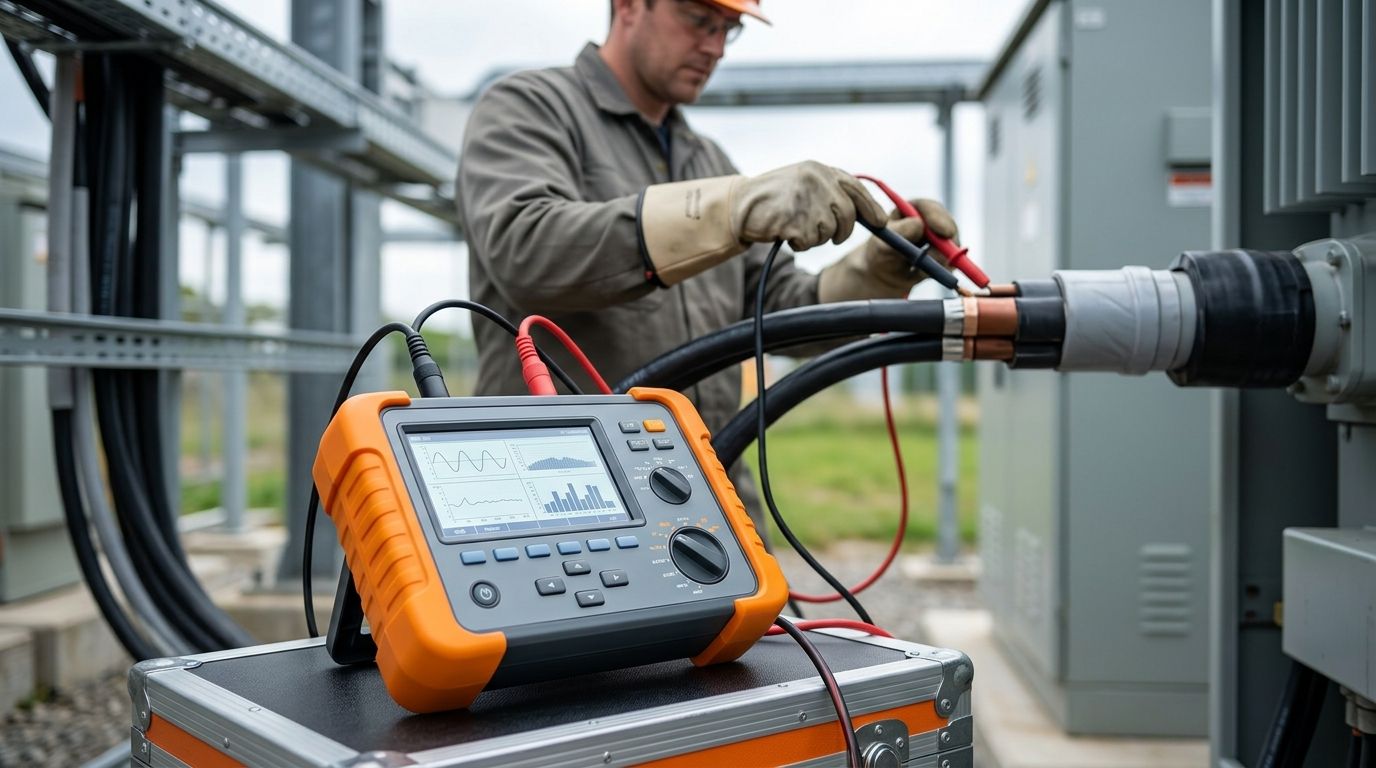
A dual-clamp stakeless tester uses clamps on an accessible grounding conductor to inject a test signal and measure the resulting current. It needs a closed conductive loop through the grounding network. Where that loop exists, it can support a practical screening check without placing auxiliary probes.
Its limitation matters most in substations: a loop reading is not automatically the resistance of the whole earth grid. A low reading can reflect multiple conductive paths. Use the result for the question the method answers, and do not substitute it for a specified fall-of-potential assessment or a selective electrode measurement.
Dual-clamp stakeless tester pros:
- Avoids auxiliary ground probes for a suitable loop test.
- Provides a way to screen accessible connections where probe placement is impractical.
- Fits repeat checks when the same conductor and method are documented.
Dual-clamp stakeless tester cons:
- Needs an appropriate closed loop; an isolated electrode is unsuitable.
- Measures a loop influenced by connected paths, not necessarily one electrode.
- Cannot replace a different test method required by the site's maintenance procedure.
Best for: Plant and substation maintenance teams screening accessible grounding loops when the required result is a loop check.
Verdict: Hold as the sole instrument for a formal grid-resistance assessment. Buy it as a screening instrument only when the loop arrangement and reporting purpose are clear.
4. Soil-resistivity-capable earth tester: best for grounding work planning
Some earth testing work concerns the soil around a grounding installation rather than the installed electrode itself. A soil-resistivity-capable tester supports probe-based measurements used to assess ground conditions for design or investigation. The reported quantity, expressed in Ω·m, is different from an electrode-resistance result expressed in Ω.
This is a procurement distinction, not a minor display setting. If a substation project includes grounding changes, the engineer may need both soil resistivity information and measurements of the installed system. Ask whether the instrument supports the required methods; do not assume an earth-resistance function also covers the project's soil-testing procedure.
Soil-resistivity-capable earth tester pros:
- Supports investigation of ground conditions for planned earthing work.
- Separates a soil measurement requirement from an installed-electrode check.
- Gives procurement teams a clear reason to specify additional measurement capability.
Soil-resistivity-capable earth tester cons:
- Soil resistivity alone does not verify installed-grid resistance.
- Requires a suitable probe layout and a defined investigation procedure.
- Adds little to a brief limited strictly to routine checks of existing connections.
Best for: Project engineers and procurement teams specifying instruments for grounding investigations alongside maintenance work.
Verdict: Buy when the written scope includes soil resistivity testing. Otherwise, specify the earth-resistance method the maintenance team will actually use.
How we ranked the configurations
The ranking follows the measurement question, then the practical constraints: whether auxiliary probes can be placed, whether the target conductor can be clamped, and whether the result must describe an electrode, a loop or the soil. A four-terminal fall-of-potential tester ranks first for a defined electrode test with workable probe geometry. Selective testing takes priority for a particular accessible electrode within a network; dual-clamp testing serves screening where a suitable loop exists.
There is no model-level performance ranking here. The supplied information names no tester models, measurement ranges, accuracy statements or certifications. Request a quote against the test method and site procedure, and ask the supplier to identify the actual instrument and documentation that satisfy them. Pan-India delivery and expert technical support make Yantratech Solutions a procurement contact for that brief, not a substitute for engineering approval of the method.
Request an earth tester quote
Share your earthing layout, test method and instrument requirements.
Which earth resistance tester should you choose?
Choose a four-terminal fall-of-potential tester by default if your 2026 substation maintenance procedure requires an electrode-resistance assessment and the site permits a valid probe layout. Choose a selective tester when the stated task is to assess an accessible electrode within a connected network. Use a dual-clamp tester for defined loop screening, not as a shortcut around the specified assessment. Add soil resistivity capability when grounding investigation is in scope.
Before approving a purchase, have the electrical engineer state what result the report must show. Procurement can then compare instruments against that requirement, while the maintenance team confirms physical access and the site safety procedure. That sequence prevents an instrument with the right category name but the wrong measurement method from reaching site.
FAQ
What is the best earth resistance tester for substation maintenance in 2026?
A four-terminal fall-of-potential tester is the best default when the required electrode test has a suitable probe layout. For an accessible electrode in an interconnected network, specify a selective tester instead.
Is a clamp-on earth tester enough for a substation earth grid?
No, a dual-clamp stakeless reading does not by itself establish the resistance of the entire substation earth grid. It measures a loop influenced by connected paths and is suited to a defined screening check.
When should I choose a selective earth tester?
Choose a selective earth tester when you need to assess an accessible electrode within an interconnected grounding network. Confirm clamp access and follow a suitable probe-based procedure.
Can I use fall-of-potential testing on a large substation grid?
Use fall-of-potential testing only with a probe layout that supports an interpretable result for that grid. Large installations can make remote probe placement and result interpretation difficult.
Is soil resistivity the same as earth resistance?
No. Soil resistivity describes ground conditions in Ω·m, while an installed electrode's resistance is expressed in Ω. Specify the measurement your engineering task requires.
What should an earth tester quote request include?
State the required test method, earthing arrangement, probe and clamp access, and reporting requirements. In 2026, ask the supplier to identify the actual instrument and documentation against that written brief.
One last thing
The most useful question before ordering is not which tester displays the lowest value. It is which physical path the instrument measures. In 2026, ask the engineer to mark that path on the earthing drawing before procurement requests a quote; it makes the distinction between an electrode test, a connected-loop check and a soil investigation explicit.